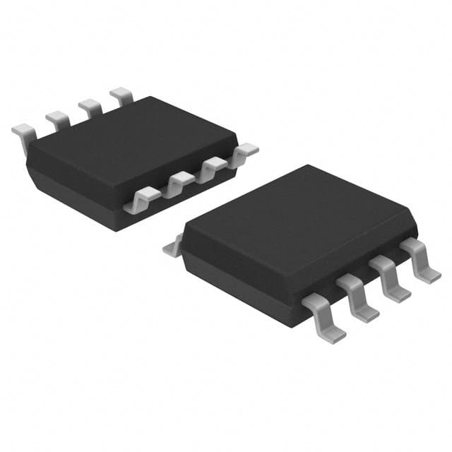
X9313WSIZT1
Product Overview
- Category: Integrated Circuit (IC)
- Use: Digital Potentiometer
- Characteristics: Non-volatile, 32-tap, 10kΩ resistance range
- Package: SOIC-8
- Essence: Provides digital control of resistance in electronic circuits
- Packaging/Quantity: Tape and Reel, 2500 units per reel
Specifications
- Resistance Range: 10kΩ
- Number of Taps: 32
- Supply Voltage: 2.7V to 5.5V
- Interface: Serial (SPI)
- Temperature Range: -40°C to +85°C
- End-to-End Resistance Tolerance: ±20%
- Resistor Network Temperature Coefficient: ±300ppm/°C
Detailed Pin Configuration
The X9313WSIZT1 IC has a total of 8 pins arranged as follows:
┌───┬───┐
   │ 1 │ 8 │
   │   │   │
   │   │   │
   │   │   │
   │   │   │
   │   │   │
   │   │   │
   │ 4 │ 5 │
   └───┴───┘
Pin Description: 1. VCC: Power supply voltage input 2. CS: Chip select input for SPI communication 3. SCLK: Serial clock input for SPI communication 4. SI: Serial data input for SPI communication 5. SO: Serial data output for SPI communication 6. GND: Ground connection 7. H0: Terminal A of the potentiometer 8. H1: Terminal B of the potentiometer
Functional Features
- Non-volatile memory: The X9313WSIZT1 retains its settings even when power is removed.
- Digital control: Allows precise adjustment of resistance in electronic circuits.
- SPI interface: Enables easy integration with microcontrollers and other digital devices.
- Low power consumption: Ideal for battery-powered applications.
- Wide temperature range: Can operate in extreme environments.
Advantages and Disadvantages
Advantages: - Non-volatile memory ensures settings are retained. - Precise digital control allows fine-tuning of resistance. - Easy integration with microcontrollers through the SPI interface. - Low power consumption extends battery life. - Wide temperature range enables use in various environments.
Disadvantages: - Limited resistance range (10kΩ). - End-to-end resistance tolerance of ±20% may not be suitable for highly precise applications. - Resistor network temperature coefficient of ±300ppm/°C may introduce slight variations in resistance with temperature changes.
Working Principles
The X9313WSIZT1 is a digital potentiometer that replaces traditional mechanical potentiometers. It consists of a resistor network and digital control circuitry. When a specific resistance value is desired, the digital control circuit adjusts the tap position on the resistor network, effectively changing the resistance between terminals H0 and H1. This digital control allows precise adjustment of resistance without the need for physical adjustments.
Detailed Application Field Plans
The X9313WSIZT1 finds applications in various fields, including:
- Audio Equipment: Provides volume control functionality in audio amplifiers and mixers.
- Industrial Automation: Used for calibration and adjustment of sensors and actuators.
- Automotive Electronics: Enables fine-tuning of parameters in automotive control systems.
- Test and Measurement Instruments: Offers programmable resistance for testing purposes.
- Consumer Electronics: Incorporates digital control in devices like TVs, gaming consoles, and home appliances.
Detailed and Complete Alternative Models
- X9C103S: 10kΩ digital potentiometer with 100 taps, SPI interface.
- MCP4131: 10kΩ digital potentiometer with 128 taps, I2C interface.
- AD8403: 10kΩ digital potentiometer with 256 taps, SPI interface.
- MAX5481: 10kΩ digital potentiometer with 64 taps, I2C interface.
These alternative models offer similar functionality to the X9313WSIZT1 and can be considered based on specific requirements.
Word count: 525 words
10个与X9313WSIZT1在技术解决方案中的应用相关的常见问题及解答
Sure! Here are 10 common questions and answers related to the application of X9313WSIZT1 in technical solutions:
Q1: What is the X9313WSIZT1? A1: The X9313WSIZT1 is a digital potentiometer, specifically a 32-tap, non-volatile, I2C interface device.
Q2: What is the purpose of using X9313WSIZT1 in technical solutions? A2: The X9313WSIZT1 can be used to digitally control resistance values in various applications, such as volume control, brightness adjustment, and voltage regulation.
Q3: How does the X9313WSIZT1 communicate with other devices? A3: The X9313WSIZT1 communicates using the I2C (Inter-Integrated Circuit) protocol, allowing it to interface with microcontrollers and other digital devices.
Q4: Can the X9313WSIZT1 store its settings even when power is disconnected? A4: Yes, the X9313WSIZT1 is non-volatile, meaning it can retain its settings even when power is disconnected.
Q5: What is the resolution of the X9313WSIZT1? A5: The X9313WSIZT1 has a resolution of 32 taps, meaning it can provide 32 different resistance values.
Q6: What is the operating voltage range of the X9313WSIZT1? A6: The X9313WSIZT1 operates within a voltage range of 2.7V to 5.5V.
Q7: Can the X9313WSIZT1 handle high currents? A7: No, the X9313WSIZT1 is designed for low current applications. It is recommended to use external amplifiers if higher currents are required.
Q8: Is the X9313WSIZT1 suitable for both analog and digital applications? A8: Yes, the X9313WSIZT1 can be used in both analog and digital applications due to its ability to control resistance values digitally.
Q9: Can multiple X9313WSIZT1 devices be connected together? A9: Yes, multiple X9313WSIZT1 devices can be connected together on the same I2C bus, allowing for control of multiple potentiometers simultaneously.
Q10: Are there any specific precautions to consider when using the X9313WSIZT1? A10: It is important to ensure that the voltage levels and current requirements of the X9313WSIZT1 are within the specified limits. Additionally, proper decoupling capacitors should be used to minimize noise and ensure stable operation.


