

IXGT15N120CD1
Product Overview
- Category: Power semiconductor device
- Use: Used in power electronic circuits for switching and controlling high voltage and high current.
- Characteristics: High voltage and current handling capability, low on-state voltage drop, fast switching speed.
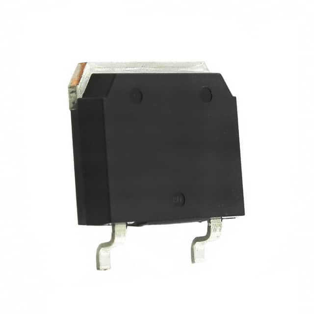
- Package: TO-268
- Essence: Insulated Gate Bipolar Transistor (IGBT)
- Packaging/Quantity: Typically packaged in reels of 100 units.
Specifications
- Voltage Rating: 1200V
- Current Rating: 15A
- Maximum Operating Temperature: 150°C
- Gate-Emitter Voltage: ±20V
- Collector-Emitter Saturation Voltage: 2.0V
- Turn-On Delay Time: 35ns
- Turn-Off Delay Time: 110ns
Detailed Pin Configuration
The IXGT15N120CD1 typically has the following pin configuration: 1. Collector (C) 2. Gate (G) 3. Emitter (E)
Functional Features
- High voltage and current handling capability
- Low on-state voltage drop
- Fast switching speed
- Low switching losses
Advantages and Disadvantages
Advantages
- High power handling capability
- Low conduction losses
- Fast switching speed
- Suitable for high-frequency applications
Disadvantages
- Higher cost compared to other power devices
- Requires careful thermal management due to high power dissipation
Working Principles
The IXGT15N120CD1 operates based on the principles of the Insulated Gate Bipolar Transistor (IGBT), which combines the advantages of MOSFETs and bipolar transistors. When a positive voltage is applied to the gate terminal, it allows current to flow between the collector and emitter terminals. The IGBT can be turned on and off rapidly, making it suitable for high-frequency switching applications.
Detailed Application Field Plans
The IXGT15N120CD1 is commonly used in various power electronic applications, including: - Motor drives - Uninterruptible power supplies (UPS) - Renewable energy systems - Induction heating - Welding equipment
Detailed and Complete Alternative Models
Some alternative models to the IXGT15N120CD1 include: - IRG4PH40UD - FGA25N120ANTD - STGW30NC60WD
In conclusion, the IXGT15N120CD1 is a high-performance IGBT suitable for high-power applications requiring efficient switching and control capabilities.
Word count: 346
10个与IXGT15N120CD1在技术解决方案中的应用相关的常见问题及解答
What is the maximum voltage rating of IXGT15N120CD1?
- The maximum voltage rating of IXGT15N120CD1 is 1200V.
What is the maximum continuous collector current of IXGT15N120CD1?
- The maximum continuous collector current of IXGT15N120CD1 is 15A.
What type of package does IXGT15N120CD1 come in?
- IXGT15N120CD1 comes in a TO-268 package.
What are the typical applications for IXGT15N120CD1?
- Typical applications for IXGT15N120CD1 include motor control, power supplies, and inverters.
What is the on-state voltage of IXGT15N120CD1 at the rated current?
- The on-state voltage of IXGT15N120CD1 at the rated current is typically around 2.2V.
Does IXGT15N120CD1 have built-in protection features?
- Yes, IXGT15N120CD1 has built-in overcurrent and short-circuit protection.
What is the maximum junction temperature of IXGT15N120CD1?
- The maximum junction temperature of IXGT15N120CD1 is 150°C.
Can IXGT15N120CD1 be used in high-frequency switching applications?
- Yes, IXGT15N120CD1 is suitable for high-frequency switching due to its fast switching characteristics.
Is IXGT15N120CD1 RoHS compliant?
- Yes, IXGT15N120CD1 is RoHS compliant, making it environmentally friendly.
What are the recommended thermal management techniques for IXGT15N120CD1?
- Recommended thermal management techniques for IXGT15N120CD1 include proper heatsinking and airflow to maintain optimal operating temperatures.