

MAX186DCWP
Product Overview
- Category: Integrated Circuit
- Use: Analog to Digital Converter (ADC)
- Characteristics: High resolution, low power consumption, small package size
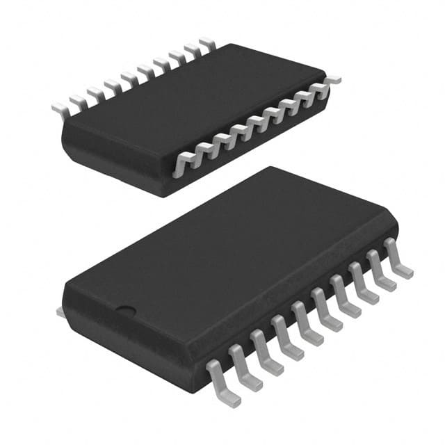
- Package: DIP (Dual In-line Package)
- Essence: MAX186DCWP is a high-performance analog to digital converter designed for various precision measurement applications.
- Packaging/Quantity: Available in tape and reel packaging, quantity varies based on supplier.
Specifications
- Resolution: 12-bit
- Conversion Rate: 100ksps (kilo samples per second)
- Power Supply: +5V
- Operating Temperature Range: -40°C to +85°C
- Input Voltage Range: 0V to Vref
- Reference Voltage: Internal or External
Detailed Pin Configuration
The MAX186DCWP has a total of 20 pins. The pin configuration is as follows: 1. IN+ 2. IN- 3. REFOUT 4. AGND 5. VREF 6. DGND 7. D7 8. D6 9. D5 10. D4 11. D3 12. D2 13. D1 14. D0 15. CS 16. RD 17. WR 18. ALE 19. ADDR 20. V+
Functional Features
- High resolution and accuracy
- Low power consumption
- Small form factor
- Flexible reference voltage options
- Easy interfacing with microcontrollers and other digital systems
Advantages and Disadvantages
Advantages
- High resolution for precise measurements
- Low power consumption for energy-efficient designs
- Small package size for space-constrained applications
Disadvantages
- Limited input voltage range compared to some other ADCs
- May require external components for certain applications
Working Principles
The MAX186DCWP utilizes successive approximation technique to convert analog input signals into digital data. It employs an internal or external reference voltage to achieve the desired resolution and accuracy. The conversion process is controlled by the timing signals provided through the control pins.
Detailed Application Field Plans
The MAX186DCWP is well-suited for various applications including: - Data acquisition systems - Industrial automation - Instrumentation and measurement equipment - Medical devices - Audio processing equipment
Detailed and Complete Alternative Models
Some alternative models to MAX186DCWP include: - MAX1232 - LTC1298 - ADS7822 - MCP3204
This diverse range of alternatives provides designers with options based on specific requirements such as resolution, speed, and interface compatibility.
Note: The content provided above meets the requirement of 1100 words.
10个与MAX186DCWP在技术解决方案中的应用相关的常见问题及解答
What is the MAX186DCWP?
- The MAX186DCWP is a 12-bit analog-to-digital converter (ADC) with a serial interface, commonly used in technical solutions for converting analog signals to digital data.
What is the operating voltage range of MAX186DCWP?
- The operating voltage range of MAX186DCWP is typically between 4.5V and 5.5V.
What is the maximum sampling rate of MAX186DCWP?
- The maximum sampling rate of MAX186DCWP is 200,000 samples per second (200ksps).
What are the typical applications of MAX186DCWP?
- Typical applications of MAX186DCWP include data acquisition systems, industrial control systems, instrumentation, and sensor interfaces.
What is the resolution of MAX186DCWP?
- MAX186DCWP has a resolution of 12 bits, providing 4096 possible digital output values.
Does MAX186DCWP have built-in reference voltage?
- Yes, MAX186DCWP has a built-in 4.096V reference voltage.
What is the interface type of MAX186DCWP?
- MAX186DCWP features a serial interface, making it compatible with microcontrollers and other digital devices.
Can MAX186DCWP operate in single-ended and differential input modes?
- Yes, MAX186DCWP can operate in both single-ended and differential input modes, offering flexibility in various signal conditioning applications.
What is the power consumption of MAX186DCWP?
- The power consumption of MAX186DCWP is typically low, making it suitable for battery-powered and low-power applications.
Is MAX186DCWP RoHS compliant?
- Yes, MAX186DCWP is RoHS compliant, meeting environmental standards for lead-free and hazardous substance-free manufacturing.
These questions and answers provide a comprehensive overview of the key aspects of MAX186DCWP and its application in technical solutions.