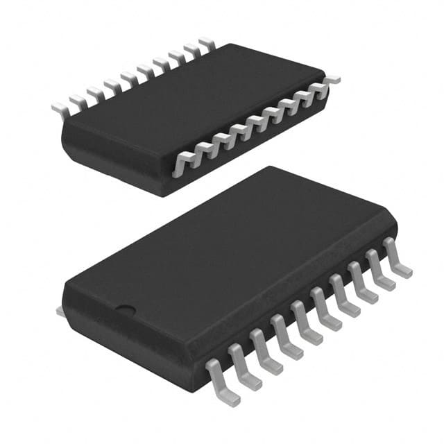
TLV5613CDWR
Product Overview
- Category: Integrated Circuit (IC)
- Use: Digital-to-Analog Converter (DAC)
- Characteristics: High precision, low power consumption
- Package: SOIC-16 (Small Outline Integrated Circuit), 16 pins
- Essence: Converts digital signals into analog voltages
- Packaging/Quantity: Tape and Reel, 2500 units per reel
Specifications
- Resolution: 12 bits
- Number of Channels: 1
- Supply Voltage Range: 2.7V to 5.5V
- Output Voltage Range: 0V to Vref
- Operating Temperature Range: -40°C to +85°C
- Conversion Rate: 400 kSPS (Samples per Second)
- Power Consumption: 0.6 mW at 5V supply voltage
Pin Configuration
The TLV5613CDWR has a total of 16 pins arranged as follows:
```
| | | 1 2 3 4 5 6 7 8 | | | | 9 10 11 12 13 14 15 16 | |_______________________________________| ```
Pin Description: 1. VDD: Positive power supply 2. AGND: Analog ground 3. REF: Reference voltage input 4. OUT: Analog output voltage 5. DIN: Serial data input 6. SCLK: Serial clock input 7. CS: Chip select input 8. DGND: Digital ground 9-16: No connection (NC)
Functional Features
- High precision DAC with 12-bit resolution
- Low power consumption for energy-efficient applications
- Wide supply voltage range allows for flexibility in system design
- Fast conversion rate of 400 kSPS enables real-time signal processing
- Serial interface simplifies integration with microcontrollers and digital systems
Advantages and Disadvantages
Advantages: - High precision output for accurate analog voltage generation - Low power consumption extends battery life in portable devices - Compact package size saves board space - Easy integration with digital systems through the serial interface
Disadvantages: - Limited to single-channel operation - May require external components for voltage reference and buffering
Working Principles
The TLV5613CDWR is a digital-to-analog converter that converts digital signals into corresponding analog voltages. It utilizes a 12-bit resolution to provide high precision output. The input digital data is received through the DIN pin and synchronized with the SCLK clock signal. The CS pin is used to select the device for communication.
The internal circuitry of the TLV5613CDWR processes the digital input and generates an analog output voltage on the OUT pin. The output voltage range is determined by the reference voltage applied to the REF pin. The conversion process occurs at a fast rate of 400 kSPS, allowing for real-time signal processing.
Detailed Application Field Plans
The TLV5613CDWR is commonly used in various applications, including:
- Audio Equipment: Provides precise analog voltage outputs for audio amplifiers and digital audio processors.
- Industrial Automation: Used in control systems to generate analog control signals for motor drives, valves, and sensors.
- Test and Measurement Instruments: Enables accurate voltage generation for calibration and signal simulation purposes.
- Communication Systems: Used in base stations and transceivers for generating analog signals in wireless communication protocols.
- Automotive Electronics: Provides analog voltage outputs for automotive control modules and infotainment systems.
Detailed and Complete Alternative Models
- TLV5614CDWR: Similar to TLV5613CDWR but with dual-channel operation.
- DAC8564ICPW: 16-bit resolution DAC with multiple channels and integrated voltage reference.
- MCP4922-E/P: 12-bit DAC with dual channels and SPI interface.
- MAX5216CPA+: 16-bit DAC with low power consumption and I2C interface.
These alternative models offer different features and specifications, providing options for various application requirements.
Word count: 515 words
10个与TLV5613CDWR在技术解决方案中的应用相关的常见问题及解答
Sure! Here are 10 common questions and answers related to the application of TLV5613CDWR:
Q: What is TLV5613CDWR? A: TLV5613CDWR is a digital-to-analog converter (DAC) IC that converts digital signals into analog voltage outputs.
Q: What is the operating voltage range of TLV5613CDWR? A: The operating voltage range of TLV5613CDWR is typically between 2.7V and 5.5V.
Q: What is the resolution of TLV5613CDWR? A: TLV5613CDWR has a resolution of 12 bits, which means it can provide 4096 different output voltage levels.
Q: How can I interface TLV5613CDWR with a microcontroller? A: TLV5613CDWR uses a serial interface (SPI or I2C) to communicate with a microcontroller. You need to connect the appropriate pins for data, clock, and control signals.
Q: Can TLV5613CDWR drive both positive and negative voltages? A: No, TLV5613CDWR can only generate positive voltage outputs. If you need negative voltages, you may need additional circuitry.
Q: What is the maximum output current of TLV5613CDWR? A: TLV5613CDWR can source or sink up to 2 mA of current from its output pin.
Q: Is TLV5613CDWR suitable for precision applications? A: TLV5613CDWR is a general-purpose DAC and may not be suitable for high-precision applications due to its limited accuracy and linearity specifications.
Q: Can I use TLV5613CDWR in a battery-powered application? A: Yes, TLV5613CDWR has a low power consumption and can be used in battery-powered applications.
Q: Does TLV5613CDWR have any built-in reference voltage? A: No, TLV5613CDWR requires an external reference voltage for generating the analog output.
Q: What are some typical applications of TLV5613CDWR? A: TLV5613CDWR is commonly used in applications such as industrial control systems, data acquisition, motor control, audio equipment, and instrumentation.
Please note that these answers are general and may vary depending on specific requirements and implementation details.


